Malware analysis
IOC - Indicators of Compromise, it’s an indicator about a potentially breach of our system, so, that can prove you have been attacked and how the attacker did. For determining the IoC, the anti-malware software analyse the system, detect signature and observe the behavior.
https://www.cloudflare.com/en-gb/learning/security/what-are-indicators-of-compromise/
Techniques of analysis
For analysis a malware, two techniques: static and dynamic.
Static
We analyse the malware without to execute it, so, that’s mean, we read the executable file for understanding how it’s works, but most of malware use techniques to avoid to be analysed, with obfuscation or packing, so, that’s mean, the content of the file is encrypted or compressed
For static analysis, we can use different tools, like the command readelf for an ELF file or pecheck for a PE (Portable Executable) file. Also, we can use the command strings for getting all string in the executable file. We can get the hash of the file, with md5sum and with virustotal, to get more information
Dynamic
For understanding how the malware works, we execute it, but in an isolated environment with no interaction with the production environment and no internet or the network connection need to be monitored.
We can deploy a virtual machine without any traffic with the production environment, called a sandbox, create a snapshot and execute the malware. Like that, we can identify how it works. When it’s over, we clean our environment, rollback to the snapshot for cleaning.
Different Open source sandbox tools are available:
- https://cuckoosandbox.org/
- https://github.com/kevoreilly/CAPEv2
- Hybrid Analysis
Unfortunately, some malware use sandbox evasion, like doing long sleep calls, user activity detection, detecting VMs.
CPU Architecture
x32 architecture
The CPU architecture below is the common CPU architecture and it’s derived from the Von Neumann architecture.
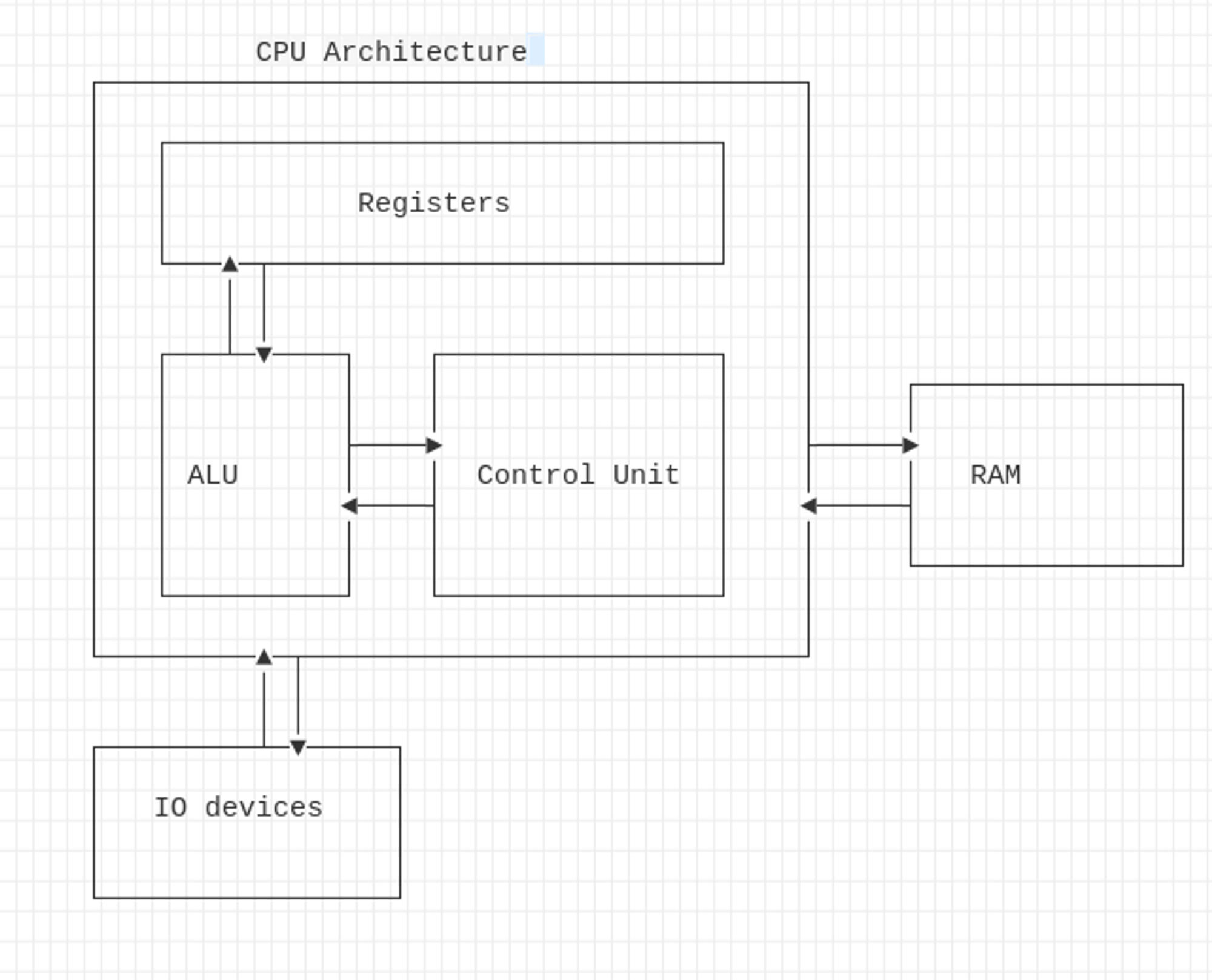
Registers: CPU’s storage which contains instructions or data. For saving time, some instruction or data are stored in these registers. The storage’s size is limited.
ALU (Arithmetic Logical Unit): Execute instruction and the result are stored in the register or in the memory
Control Unit: Get the instruction from the RAM, the address to the next instruction is stored in the IP (Instruction Pointer) register: EIP for 32bits and RIP for the x86 architecture.
Registers
The Instruction Pointer (IP): contain the address to the next instruction to be executed by the CPU. In 32bit, the IP is called EIP (Extended IP) and for 64bit, called RIP (Register IP).
The General-Purpose Registers represents registers in CPU architecture. We can find these commons registers:
| Register | 32 bits | 64 bits | Comment |
|---|---|---|---|
| Accumulator | EAX | RAX | It’s used for arithmetics, logical and I/O instructions |
| Counter | ECX | RCX | It’s a counter for loops |
| Data | EDX | RDX | Also used for I/O instructions |
| Base | EBX | RBX | It’s a index for the value |
| Pointer | ESP | RSP | It’s the stack pointer of the current data |
| Pointer | EBP | RBP | Pointer to the base of the current stack frame |
| Index | EDI | RDI | Pointer for manipulating string |
| Index | EIP | RIP | Contain the next instruction pointer |
| R8-R15 |
For EAX or RAX register, when we do an arithmetic operation, we move the value from the RBP or EBP register to the EAX/RAX register and do the operation. For instance, in the example below, we move the value from RBP, do an XOR operation and move the value to the RBP:
mov    -0x8(%rbp),%eax
xor    $0x1,%eax
mov    %eax,-0x4(%rbp)
Segment registers
A segment register hold in 16bits, is a special pointer which identify a segment in the memory:
| Segment | Description |
|---|---|
| Code Segment (CS) | Pointer to the code section in the code section |
| Data Segment (DS) | Pointer to the program’s data section |
| Stack Segment (SS) | Pointer to the program’s stack |
| Extra Segment (ES, FS and GS) | Pointers to differents section in the code |
https://www.sciencedirect.com/topics/computer-science/segment-register
Memory
The diagram below show the architecture of the memory:
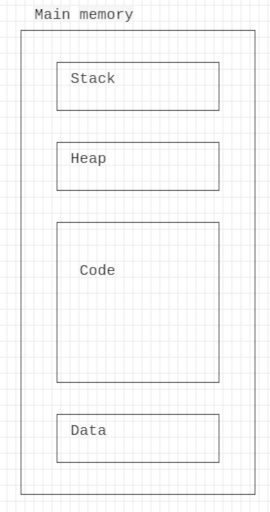
The code section contains all the code of the program loaded into the memory
The data section contains all initialized data
The heap section contains all dynamic allocation variables, initialized with malloc
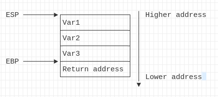
The stack section contain all local variables. It’s LIFO (Last In, First out) stack, that’s mean, the first local variable has a higher address and the last variable has a lower address.
OpCode
OpCode is the instruction for the operation encoded in hex. Each operation in assembler like CALL, MOV, RET, LEAVE, etc, are encoded in hex. You can find these opcode in this website:
http://ref.x86asm.net/coder64.html
For instance, for the operation RET, the code is 0xc3. When we disass a code with gdb, we can check that:
(gdb) disas /r main
Dump of assembler code for function main:
   0x0000000000001149 <+0>: f3 0f 1e fa endbr64
   0x000000000000114d <+4>: 55  push   %rbp
   0x000000000000114e <+5>: 48 89 e5    mov    %rsp,%rbp
   0x0000000000001151 <+8>: 48 83 ec 10 sub    $0x10,%rsp
   0x0000000000001155 <+12>:    c6 45 ff 61 movb   $0x61,-0x1(%rbp)
   0x0000000000001159 <+16>:    0f be 45 ff movsbl -0x1(%rbp),%eax
   0x000000000000115d <+20>:    89 c6   mov    %eax,%esi
   0x000000000000115f <+22>:    48 8d 05 9e 0e 00 00    lea    0xe9e(%rip),%rax        # 0x2004
   0x0000000000001166 <+29>:    48 89 c7    mov    %rax,%rdi
   0x0000000000001169 <+32>:    b8 00 00 00 00  mov    $0x0,%eax
   0x000000000000116e <+37>:    e8 dd fe ff ff  call   0x1050 <printf@plt>
   0x0000000000001173 <+42>:    b8 00 00 00 00  mov    $0x0,%eax
   0x0000000000001178 <+47>:    c9  leave
   0x0000000000001179 <+48>:    c3  ret
And in the hexdump, at the entry 1179, we can see the OpCode for the return operation (at the adress 0x11f8):
hexdump main | grep 1170
0001170 fffe b8ff 0000 0000 c3c9 0000 0ff3 fa1e
In the figure below, it’s an extract from the website x86asm, we have the explanation of the code 0xC3 which is for the return.

General instruction
MOV: move the value from one location to a new location: mov destination source. For instance, move the value from the value 0x61 (’a’) to the $rbp: mov $0x61, -0x1(%rbp)
LEA (Load Effective Address): like move, which move the data to the destination, LEA move the address to the destination. For instance, copy the address of the variable to the destination. For instance the code following: int *b = &b;. Will generate the assembly code: lea -0x14(%rbp),%rax.
NOP: that instruction do nothing
SHIFT: Shift register bit to the adjacent bit, we can shift to right and to the left with shr and shl instruction: shl destination, count or shr destination, count.
http://www.c-jump.com/CIS77/ASM/Assembly/A77_0380_shl_shr.htm
Rotate: Similar to the shift, but bits are rotated. We can rotate to the left and to the right with ror or rol instruction.
ADD: Add instruction is the arithmetic operation for the addition (add destination, value). The C code follow: int b = a + 10; , generate the assembly code:
mov -0x8(%rbp), %eax
add $0xa, %eax
SUB: Instruction for the substraction. The C code following: int b = a - 5, generate the assembly code bellow:
sub $0x2,%eax
DIV: use for the division operation: div value.
MUL: use for the multiplication: mul value.
INC: Increment the value by one: inc eax
DESC: decrement the value by one: dec eax
AND: logical instruction, performs a bitwise AND operation: and $0x1,%eax
OR: logical instruction, performs a bitwise OR operation: or $0x1,%eax
XOR: logical instruction, performs a bitwise XOR operation: xor $0x1,%eax
NOT: logical instruction, inverts the value 0 by 1 and vice-versa.
Flags
When an operation is executed, the CPU has different flags for the outcome. The tableau below show the common flags:
| Flag | Description |
|---|---|
| Carry (CF) | Set when a carry-out or borrow is required from the most significant bit in an arithmetic operation. Also used for bit-wise shifting operations. |
| Parity (PF) | Set if the least significant byte of the result contains an even number of 1 bits. |
| Auxiliary (AF) | Set if a carry-out or borrow is required from bit 3 to bit 4 in an arithmetic operation (BCD arithmetic). |
| Zero (ZF) | Set if the result of the operation is zero. |
| Sign (SF) | Set if the result of the operation is negative (i.e., the most significant bit is 1). |
| Overflow (OF) | Set if there's a signed arithmetic overflow (e.g., adding two positive numbers and getting a negative result or vice versa). |
| Direction (DF) | Determines the direction for string processing instructions. If DF=0, the string is processed forward; if DF=1, the string is processed backward. |
| Interrupt Enable (IF) | If set (1), it enables maskable hardware interrupts. If cleared (0), interrupts are disabled. |
If we want to display the CPU flags with gdb:
info registers eflags
eflags         0x246               [ PF ZF IF ]